Introduction
Just about one year ago, late in the summer of 2023, I made the decision to actually give film photography a try. I had already been using manual vintage lenses on my digital camera for many years and digital was beginning to feel old to me, I wanted to try something new! I’ve had my mom’s Olympus OM-1 sitting around with a roll of Kodak 400TX partially exposed and subsequently forgotten about since 2014 and it was time I cracked it back out and hopped onto the analog photography revolution!
Except… The poor OM-1 had been sitting around for years mostly forgotten, even before I got to it in 2014. It was just a bit worse for wear. Before moving forward with it, I shipped the body off to John Hermanson (aka Camtech) who was (and is at the time of writing) one of the best camera repair techs for Olympus OM cameras to give the whole thing a tune-up cleaning, lubrication, and adjustment - or CLA. After several agonizing months of waiting - which I filled by shooting on a Minolta SRT 200 I also happened to have on hand - I got the OM-1 back with a new prism installed (the original had serious damage due to the insulating foam deteriorating and eating away at the mirrored surface) and modified to take 1.5V Silver Oxide battery instead of the original Mercury battery (which is no longer available to purchase). With my OM-1 ready for action I ran several rolls of film through it!
But this all got me thinking: all of the formally trained camera technicians (like John Hermanson) were trained and working back in the 70’s and 80’s, they’ve been in business a long time now and are probably looking to retire! As a matter of fact, John recently shared that he’s downsizing which cameras he’ll take for CLA’s in an effort to move toward retirement. This all made me consider that the previous generation of film camera repair techs are already scarce and they’ll only become more rare as time goes on. I wanted to do something about that, specifically so that I’d personally be able to keep my cameras operating.
That brings us to the topic of this blog, my journey into learning camera repair and maintenance. I decided I would focus solely on Olympus OM-1’s to start out. The reasoning for this extends a bit beyond just the fact that it’s what I own (though that’s the main driving factor) but also because the OM-1 is a fully manual camera. The only thing it uses batteries for is its light meter, so even without batteries it’s capable of full operation as long as you have some external way of measuring your exposure. This - to my inexperienced mind - makes the OM-1 a more serviceable camera because I’d never battling faulty PCB’s, photocells, or wires to get the camera to a point where it will actually take photos. Instead I’m faced with extremely complicated watch-like mechanisms to fiddle with - cool!
Because I wasn’t about to make my mom’s camera a sacrificial learning tool in case I fail tremendously, I went to eBay and purchased several junker OM-1’s all listed as “not working” or “for parts” that I could pull apart and attempt to bring back to life!
This inaugural blog post is going to be a slap-dash and poorly chronicled journey through my first dive into the world of camera repair. I spent more time learning than documenting the process this time so consider this a taste of what I’m hoping this blog can be. So, without further ado, let’s take a look at the first victim camera I worked on!
OM-1 MD - “Broken Light Meter”
I’m trying to give each camera I repair a unique name to help differentiate them from one another. This one is named “Broken Light Meter” thanks to its most defining trait/fault.
Initial Overview
This is an OM-1 MD, the second flavor of OM-1 that Olympus manufactured between 1974 to 1979. The only difference that I know of between the MD and non-MD variants is the ability for the MD version to more easily couple with a motor drive (hence the MD name) without modifications. This means it has a slightly different bottom plate and mildly different internals - but hopefully similar enough where what I learn on the MD is transferable to the non MD models.
Problems Diagnosed During Initial Inspection:
This camera was listed on eBay as having a broken light meter, which seemed to be accurate. The meter would not move at all when turned on with a battery installed.
The prism showed minor damage from the insulating foam around it and the hot shoe base, meaning the foam needed to be removed promptly.
The “bulb” setting on the shutter would not behave correctly, instead of holding the shutter open for as long as the release is held the shutter would close on its own.
The light seals needed replacing, they were all old and crumbling
Overall, the camera was in decent enough shape, this didn’t feel too daunting aside from the fact that I had zero experience with camera repair. So, I downloaded and consulted the service manual and dove in!
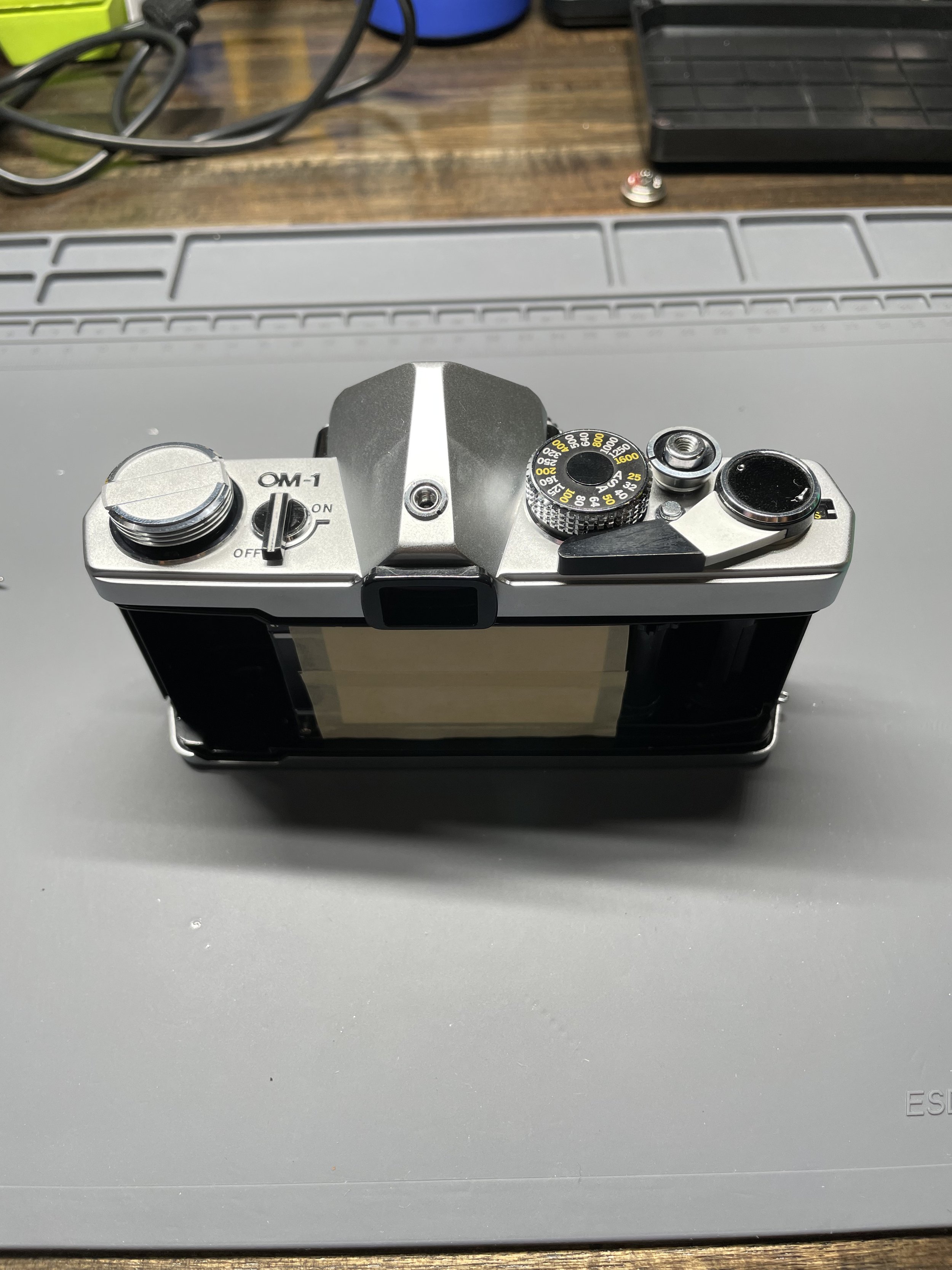
The camera in question after a bit of initial inspection and prep. I taped a piece of cardstock over the shutter from the back to help protect it - not sure how necessary that was but I did it anyway!
Removing the Prism Foam
I started with the removal of the prism foam as that was probably the easiest way to get my hands dirty and get into the camera and prove to myself that it’s not quite as scary to open up as it may seem. Several youtube tutorials and reviews of the manual later I had the top cover off and the foam removed! The prism was still a bit damaged, but not horribly and the camera was still extremely useable despite relatively tiny artifacts visible in the viewfinder due to the prism desilvering. If I was tuning this up for someone else I’d probably consider a prism replacement, but this first repair was for me so I wasn’t too worried about it.
The camera with its top plate removed, this is after the foam removal. Normally the foam would be below the hot shoe base and covering the wires that can be seen running over top of the viewfinder.
While inside of the top plate I took a look at the light meter circuit to see if there was any obvious issues that could be fixed quickly. I noticed that the brown wire that led up from the battery compartment in the bottom of the camera was soldered to a pretty corroded contact on the switch, but even after a crude re-solder and test with a 1.35v battery the meter wouldn’t come to life, something deeper was wrong with it. Time to move on to the bulb setting issue and circle back to the meter later.
The brown battery wire's contact was so corroded that the wire actually snapped off after just a bit of poking.
Showing off my novice level soldering to re-attach the wire to its contact on the switch.
Fixing the “Bulb” Shutter Setting
The OM cameras, much like many other cameras, have a “bulb” shutter setting which allows the photographer to hold the shutter open for as long as they hold the shutter release down to allow for exposures longer than the internal timer can manage. This particular camera had issues with its bulb setting, it would only hold the shutter open for a small duration before closing it again while the release was held. This fix would mean getting into the shutter speed controls by separating the mirror cage/box from the camera body. This is where I probably should have spent a bit more time consulting the manual on how to execute this maneuver because I made several mistakes the first time around.
The most notable mistake that’s worth mentioning here is not knowing that I needed to desolder several wires from the bottom of the camera in order to free the mirror cage from the body. The white and red wires pictured below are all part of the flash circuit, specifically they work to determine when the flash should get triggered based on the position of the flash mode switch near the lens mount (WITH the shutter in X mode, or slightly before the shutter release in FP mode). The reason these wires are down here is because they’re connected to some contacts that live in between the connection that triggers the mirror and shutter mechanisms, these contacts get squeezed together by these connecting parts and send the signal to fire the flash when in FP mode.
This is all great to know in hindsight, but what a trained camera technician (or one who took the time to read more of the manual) would know is that the wires that run between the flash mode switch on the mirror cage and the contacts in the bottom of the camera need to be desoldered so they actually come out along with the mirror cage instead of getting ripped out of their contacts in places that are difficult to reach… which is exactly what I did during my first mirror cage removal attempt.
This is a photo from right after I removed the mirror cage for the first time that shows the white and red wires in the bottom of the camera. This is the side of the camera opposite of the battery compartment and the camera is currently oriented so that the mirror cage would have been pointing toward the top of the photo if it was still installed.
Notice the white and red wires dangling out the front of the camera toward the top of the photo. Those were supposed to get desoldered from the bottom of the camera and come out with the mirror cage, not get ripped out of their solder contacts. Oops.
Here's the same view with the red wires desoldered (what do you know, Olympus even had a convenient joint in the wires designed TO get desoldered for disassembly - very convenient if only I hadn't overlooked it!) and with the motor drive contacts removed. The FP flash trigger contacts are circled in yellow, when the camera is fully assembled that area has several interconnects in it that push those contacts shut when the shutter button is pressed to trigger the flash.
This white wire is supposed to be connected, not loose in my hand.
Annotated circuit diagram from the OM-1 service manual. The blue circle is where the white wire is supposed to be connected
In the lefthand photo above we can see the fatal mistake made by not properly desoldering the flash circuit wires from the bottom of the camera, I had ripped the red and white wires from their contact points. This photo was taken after I had reconnected the red wire to the switch, but the white wire that I'm holding in the photo is supposed to be soldered to a contact where the other white wire leading to the hot shoe base is connected to. Getting to that contact would involve serious disassembly of the mirror cage and I personally am not yet up to that task. After consulting the circuit diagram to confirm, I was relatively confident that the white wire that ran up to the hot shoe base and the white wire that ran to the FP sync contact in the bottom of the camera meet at the same solder point. With that knowledge I decided to simply bypass the contact in the switch and instead run a new, longer white wire up to the solder point for the hot shoe base and connect the FP contact that way. Fortunately, this workaround seems to work just fine, when testing the camera after all repairs were complete the FP flash sync does in fact fire a few milliseconds before the first curtain opens - success ripped from the clutches of failure!
Now that I was finished fixing the problem I had created, it was time to figure out why the bulb speed setting was acting up. Astoundingly, after poking around for a short time and temporarily re-attaching the mirror cage to the body to troubleshoot, I realized that the gear that couples the shutter speed setting near the lens mount to the actual shutter release assembly was off by ONE TOOTH. This apparently is enough to throw the whole system out of whack and stop the bulb setting from firing correctly. Re-aligning the 1/1000 second timing hole with the final tooth of the shutter speed ring fixed the problem up right away!
The mirror cage temporarily placed back onto the body. This photo has the shutter speed gear cover and shutter gear plate removed - normally with those installed you can't see these gears that live right below the mirror. Notice that the last tooth of the shutter speed gear is lined up with the timing hole of the gear it mates to. That timing hole indicates 1/1000 second shutter speed and wants to be aligned with the final tooth of the gear.
Mirror cage re-installed with my replacement white wire now running to the bottom of the camera all the way from the hot shoe base.
Resoldering the three red wires back together proved to be a real chore, even with some helping hands! I wound up doing a bunch of trial and error before getting them back together - but not before snapping the wires apart in a few places. I need to find a better method for this part.
Fixing the Broken Meter
A couple weeks after beginning the project, it was time to return to the broken light meter. I was very close to giving up and deciding that the camera would simply be meterless, but I still had a couple things I knew I could try.
First, I tested continuity of the wire running from the battery up to the meter circuit. Aha! No continuity, the wire was corroded thoroughly and needed replacing. Once again I pulled the mirror cage off and got to the process of removing the old brown battery wire and replacing it with a fresh one - this time it’ll be black because I don’t have a brown replacement, oh well!
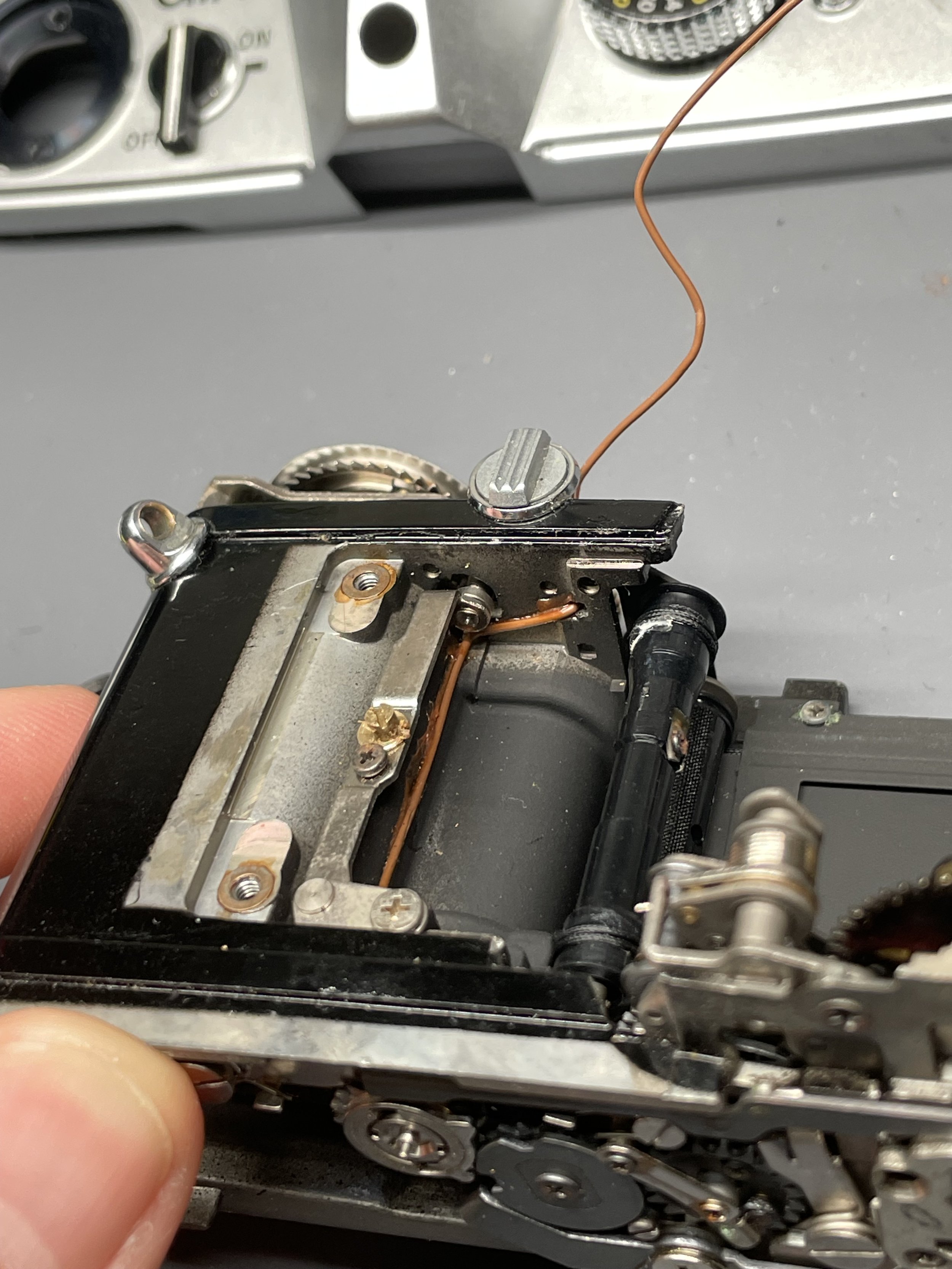
The battery wire disconnected from the (currently removed) battery compartment. We can see it running off to the right of this photo where it enters a small access hole after that blob of glue to run up the inside of the camera.
The battery wire running up the inside of the camera, this is inside the camera behind the film take-up spool.
The battery wire poking up through its access hole at the top of the camera, from here it would normally run over top of the prism to get around to the rest of the meter circuit.
I didn’t take many photos of the actual wire replacement, but they’d likely look a lot like the photos above with a different color of wire. While replacing the battery wire I also added an 1N34A diode into the circuit to allow the camera to take 1.5v button cell batteries instead of the original 1.35v mercury battery it was designed for. This mod does come with the need to adjust the meter a bit, but we’ll get to that later!
The new battery wire installed with an 1N34A diode added in-line. It's not the prettiest thing, but it's glued down and secure which is the most important part!
Finally, after replacing the battery wire the light meter… still didn’t work!! I was running out of ideas. Fortunately, right around this time, a veteran camera technician made a post on his blog about what can potentially go wrong with the OM-1’s meter over time and he mentioned that on occasion the contacts of the actual battery switch itself can also get corroded and stop the meter from working. I was out of ideas, so into the switch we go!
Removing the plastic cover that protects the switch. This photo already shows that the problem is definitely corrosion on the switch's contacts, look how green they are (yellow arrow)!!
This photo also shows my bonus second white wire added onto the hot shoe base contact.
Some isopropyl alcohol and cotton swabs later and the contacts were MUCH cleaner than they started out and the light meter worked once again!! This was probably the most exciting part of the repair to have success in.
All that was left was to replace the light seals and recalibrate the meter.
Replacing the Light Seals
I saved the other easy part of this repair for the end just in case things went south I didn’t want to waste my time and materials replacing the light seals if the camera wound up dead by my hand anyway.
Light seals on film cameras are enormously important for preventing light from getting into the film compartment from any direction other than through the lens and shutter. Over time this foam needs to be replaced since it’ll deteriorate like all foam tends to. There are some really great articles about replacing camera light seals that I followed, so I won’t go into incredible detail here. In short, I removed all of the old crusty foam, cut some new strips to size, wet the adhesive backing with water (so it didn’t stick immediately), and slapped those bad boys in there (with more trial and error than I’m implying here).
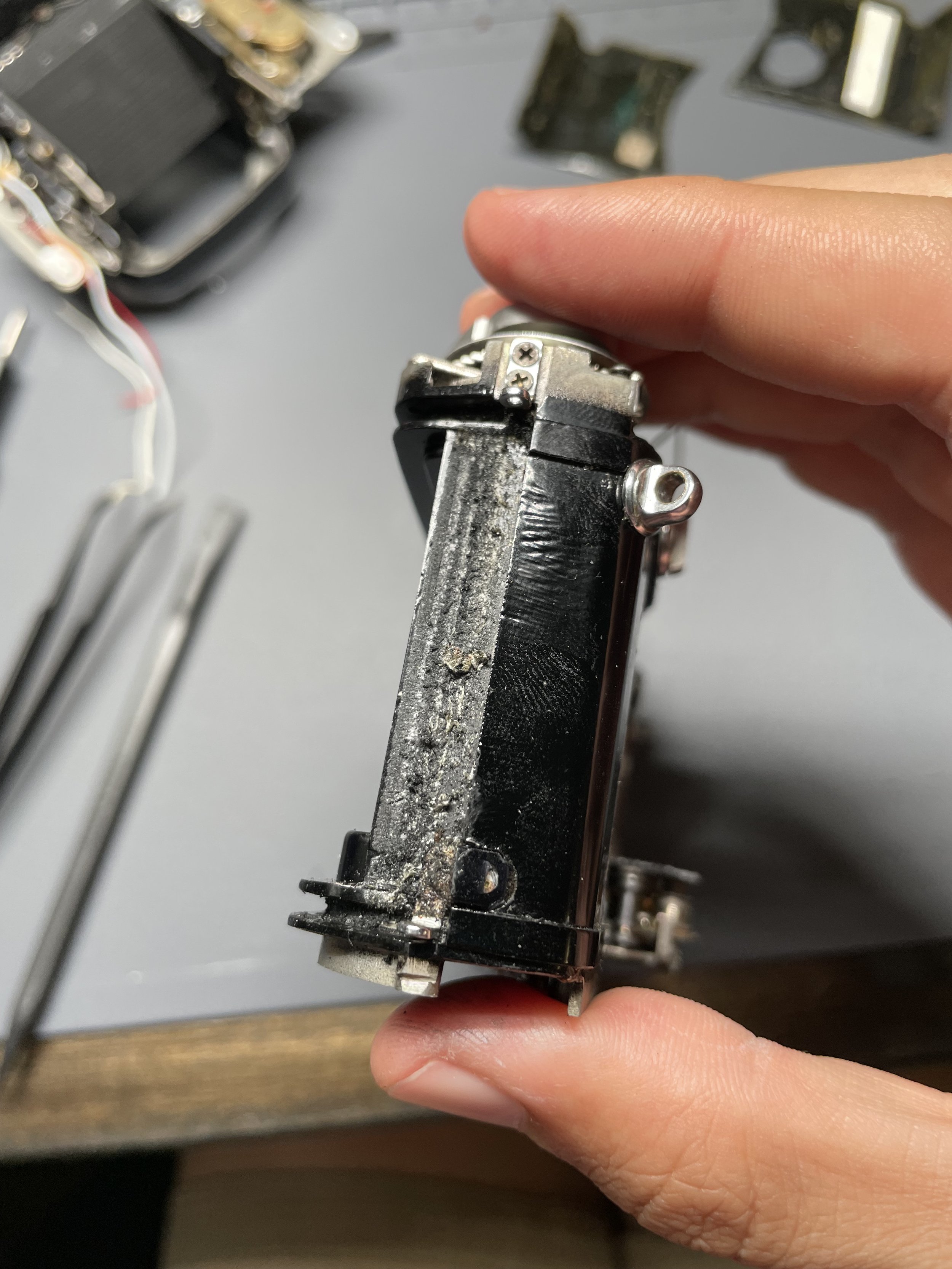
The old foam can be seen in the grooves around the film compartment.
Eagle eyed readers will notice that I'm telling this story out of order, yes this DID happen before I replaced the battery wire and while the mirror cage was still removed. Don't think about it too hard!
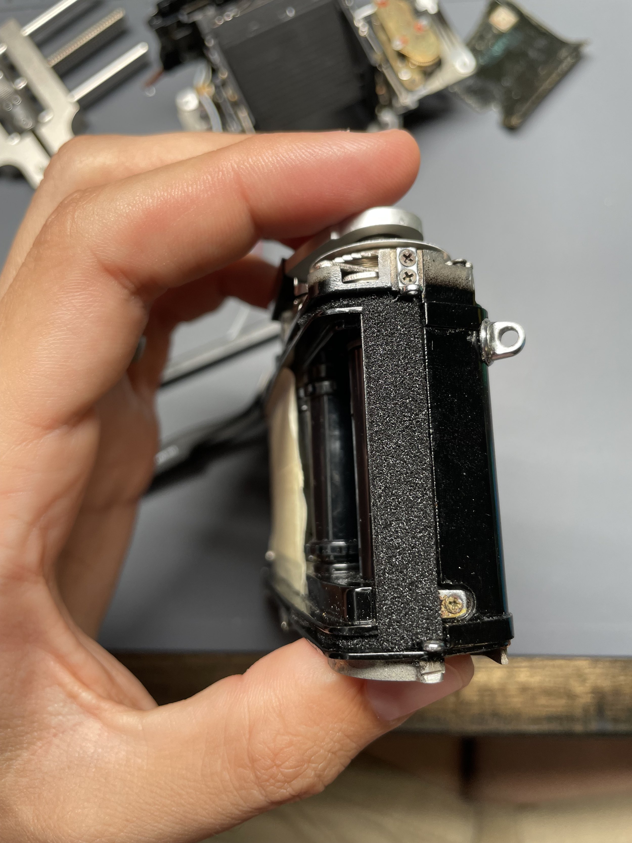
Rear foam replaced!
The old foam from the film take-up side of the camera.
Side foam replaced!
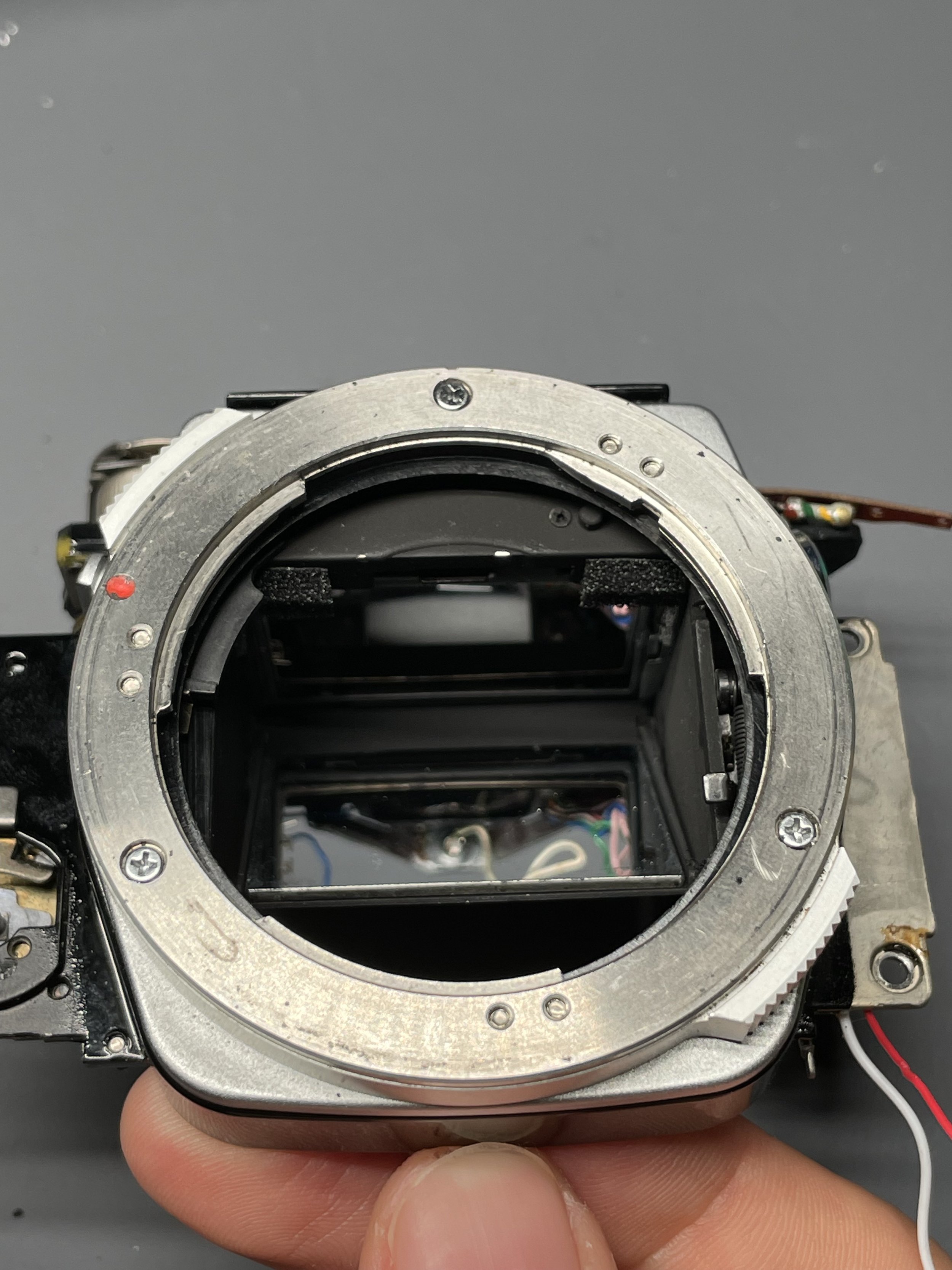
The old foam that absorbs some of the mirror slap impact in the mirror cage.
Mirror foam replaced!
Finally, all that was left was to calibrate the meter, re-attach the camera leatherette, and close it all up!
Re-Calibrating the Light Meter
How the camera looked toward the end of the process. Notice the self timer lever also had to be removed to get the mirror cage separated.
Yes, technically this is after the light seals but before the battery wire was replaced. I told the story out of order, but it's narratively better this way so pretend like it all makes sense anyway please!
Normally, the OM-1 will have its meter “zero’d” (the needle will land at the “correctly exposed” center point) when the camera has a lens attached and the exposure settings are set to ASA 1600, aperture of f/8, and a shutter speed of Bulb. Though, there’s often a need to adjust this zero point, one of those times includes adding in a diode to allow the meter to take 1.5v batteries. In order to make the meter accurate again, I needed to adjust the needle’s zero point.
Fortunately to add to my toolbox for this new hobby, I purchased a camera tester from Reveni Labs which has a built in LED that’s calibrated to specific EV levels to aid in setting camera light meters. I dropped the newly re-assembled camera onto the tester and ran it through several EV levels while shifting the eccentric screw on the galvanometer which adjusted the meter’s reading to match the output of the LED panel.
Loosening the locking screw on the galvanometer that allows for the eccentric screw to be adjusted
Turning the eccentric screw to shift the position of the meter needle at a given setting
The newly calibrated camera now has a mostly accurate meter (it reads slightly under at lower EV levels, likely due to mild variances thanks to the diode mod, but still serviceable enough for field work if you ask me) and I also ran it through some shutter speed tests on the camera tester. It turns out that this OM-1 has the most accurate shutter of all of my functioning OM-1’s so far, the only speed that’s out of spec is 1/8 second, where it’s just 2 milliseconds slower than the tolerances listed in the service manual and technically 17 milliseconds slower than true 1/8 second. But all other speeds are within the tolerances and honestly, I’ll accept 2ms off spec on just one speed!
I’ve been shooting on this camera primarily after its repair and will share the results once the rolls are developed, scanned, and edited (so who knows when I’ll actually get around to it, but I’ll share once I do!)
The finished camera after some time in the field - working flawlessly (well, I hope, we'll see how the film turns out)!
I have the camera equipped with one of my Peak Design micro clutches, which fit these OM-1's beautifully!
Conclusion
That’s all for this blog post to kick off my Olympus OM camera repair journey. My goal for future posts is to be a bit more thorough in my descriptions and photos so that these can hopefully become a resource both for myself to come back to and reference and for other aspiring camera repair techs who want to learn how to service these machines. Resources for how to do these repairs are surprisingly scarce compared to other repair tutorials online and I want to do my part to contribute to the accessible knowledge base! Thanks for joining me on this one, hope you come back for the next blog!


